|
You are visitor # 83596
In this article I analyze some of the PTgui's advanced functions: t1 and t2 control points, the Optimizer advanced mode and finally the panorama creation with the various “Layers “ output options.
Last review: March 2008. Added some notes about compatibility with PTgui 7.
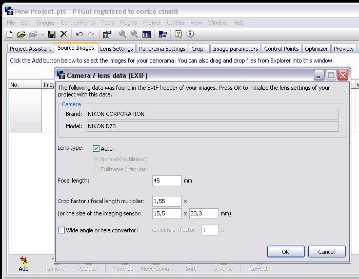
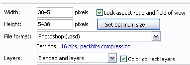
PTGui 5.7 Before starting, we would like to present some news included in the last release of PTGui, the 5.7 issued on March 2006: - support for PSB Photoshop output format, which permits to realize very large dimensions images, until 300.000x300.000 pixel, exceeding the previous barrier of 4G byte as maximum dimension for an image; - on Tools/Options/Directories&Files we can configure until 5 drives/folders at the same time for temporary files, to greatly expand the storage space; - EXIF data are read also by TIFF files (in addition to JPGs), that is a very useful function for people who shoot in RAW format and subsequently converts in TIFF format: in this way, the focal length of utilized lens and the sensor size are imported automatically. In this new version there are also some code optimizations, so that we advice the upgrade also to people who are not interested on above mentioned news.
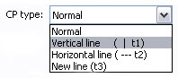
Control Points t1 and t2 In addition to “normal” Control Points, there are other two types of Control Points, “t1” (vertical line) and “t2” (horizontal line) that can be utilized to line up correctly a Stitch and to execute perspective corrections on images. In the list we find also a “t3” (line) which was supported by Panatools but actually it’s not supported by PTGui.
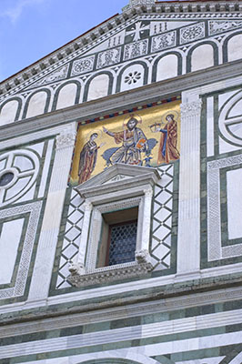
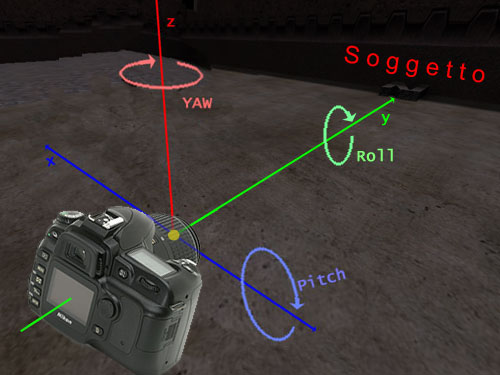
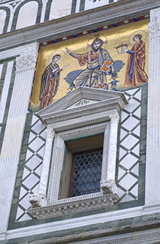
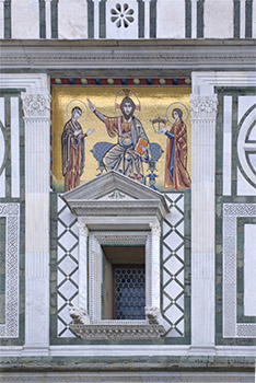
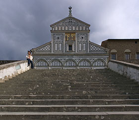
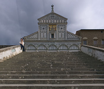
To better understand CP t1 and t2 capacities, we examine a single image which shows the front side of Church in S. Miniato a Monte, Florence (Italy).
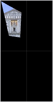
To point out the perspective correction, the image has been framed from a not optimal point. Our aim is to rebuild a “correct” mosaic view, as framed from a frontal position. To execute this operation, we can use PTGui extremely powered tools as t1/t2 Control Point and the "advanced mode" Optimizer. We have to specify to PTGui a series of straight lines that define horizontal and/or vertical axis of the scene: these data give indications about shooting parameters Yaw/Pitch/Roll that, together with the field of view of the used lens, will allow a perfect perspective correction. Please follow the operations to execute.
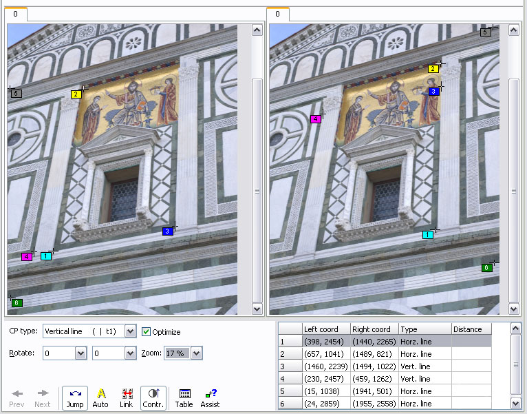
PTGui 5.7 recognizes automatically the shooting data, extracting them from EXIF data on TIFF file. However we need to control every time the correctness of these data before proceeding. At this point we enter directly to “Control Points” panel:
The entered control points don’t define - as previously told - the correspondence points between images, but straight lines that actually are placed vertically or horizontally. The front side of S.Miniato a Monte church helps a lot us in this operation, thanks to the abundance of ortogonal references. As you can see, PTGui opens two windows (also if the image is one) and the reference points are entered one for each image. CP1, for example, defines an horizontal line which ends are indicated in the two windows. The same thing is for CP2, 5 and 6 (horizontal) and for CP3 and 4 (vertical). To obtain an exact calculation, we have to enter more horizontal and vertical lines covering all the image. Poor or not well distribuited control points will lead in higher calculation errors. In the panel “Panorama settings” we have only to set the rectilinear projection (Rectilinear -flat). Nel pannello "Panorama settings" si deve solamente impostare la proiezione rettilineare (Rectilinear -flat).
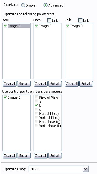
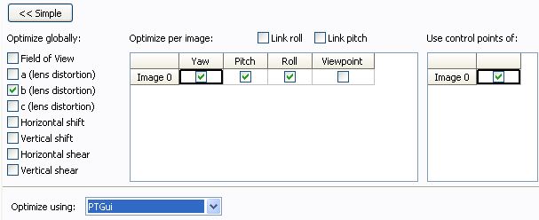
In the Optimizer advanced mode, it’s possible to select individually which parameters optimize automatically and which that haven’t to be optimized, maintaining in this manner the assigned value for default. Concerning the camera pointing parameters (Yaw, Pitch, Roll), I decided to optimize all of them, because during the shoot the camera was rotated on all the three axis (in particular it was pointed to the up/left and lightly rotated). For example, if I was sure to have put the camera aligned to the XY planes (with a spirit level), I wouldn’t optimized the relative parameters but I would have maintained Roll=0 and Pitch=0. In fact, the default value of all parameters is zero. In the list “use control points of” we have to specify which control points use. Usually, all control points included in the project are utilized, so we check all option-boxes. In our example, we checked “Image 0” that is the unique image in the project. In the list “lens parameters”, instead, we have to specify which lens parameters need to be optimized. The principle is always the same: we will not optimize the parameters we exactly know, but we will find automatically with PTGui those unknown and uncertain, checking the corresponding option-box. Concerning the “Field of View” of the lens, I preferred to maintain the previously set up value (unchecked option-box), as I do for “Shift” values (theoretically equal to zero) “Shear” values haven’t a sense for the images captured by a digital camera, so that they never have to be optimized. Before checking optimization result, I answer a question that probably you have: considering that Optimizer permits to check all parameters relative to camera position and also those relative to used lens, why we can’t select all of them? Well, we can imagine PTGui optimization as a complex mathematic equation where bigger in the number of unknown parameters, bigger is the possibility to have inconsistent results. Vice versa, fixing the value of some known values, we focalize the calculation only for really unknown variables. At this point we are able to start optimization, clicking “Run Optimizer”:
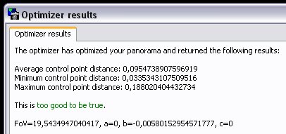
The numerical results of optimization process seem very good (PTGui specifies “too good to be true”) but we suggest to verify the work opening “Panorama Editor” (Ctrl+E). If the final result is visually satisfactory, we proceed to create the final Stitch, selecting “Lanczos” interpolation mode (to guarantee the best interpolation quality). I risultati numerici dell'ottimizzazione sembrano molto buoni (addirittura PTGui sottolinea "troppo buoni per essere veri"!), ma è buona norma verificare il lavoro svolto aprendo il "Panorama Editor" (Ctrl+E). Se il risultato finale ci soddisfa, si procede alla creazione dello Stitch finale, selezionando il metodo di interpolazione "Lanczos", per garantire la miglior qualità del risultato.
In the above images, we have summarized the complete procedure to correct the image perspective. Starting from left, we find: - a. the cut out of the interested zone on the original image - b. the reconstruction of the correct image as it appears in the “Panorama Editor” window. From here it’s already possible to note the validity of calculations, because the image seem to be substantially correct. - c. in the next image we can see the cut out of the final Stitch, where the subject proportions seem to be correctly reproduced - d. in the final image we have super-imposed the Photoshop grid, to verify the very good correction of horizontal and vertical lines. The result is geometrically excellent. Vertical and horizontal lines have been reconstructed very well and also the distortion appears under control, that means that Optimizer disposed enough and well distributed t1/t2 references.
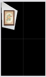
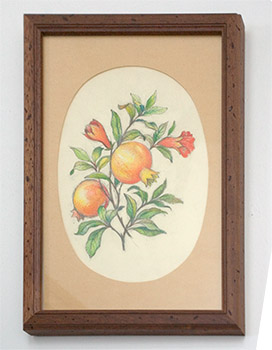
The images are in the same sequence as for S.Miniato. The measure of frame is 20.7x30.5 cm with a ratio between sides of 1.475, and in final Stitch I measured 1616x1078 pixels with a ratio of 1.499. At the first attempt, the optimization of this project doesn’t give a good result (unacceptable, very high "b" value), so I decided to enter manually the exact "b" value of the lens (-0,0058) and then optimize with "b" disabled.
Before finishing this argument, we analyze another case in which t1 and t2 control points can be used: the alignment of a panorama Stitch. Indeed, t1/t2 can be used together with “normal” CP used for to joint images. When we have a panorama Stitch with a not well aligned horizon, it’s possible to operate manually on “Panorama Editor” or it’s possible to add a t2 control (horizontal) to draw a virtual horizontal line between the first and the last image. After the optimization, our image will be levelled without any manual operation. The same workflow is valid also for vertical lines, using CP t1 (verticals). However, PTGui can’t completely satisfy the requested conditions if during calculations it will find “inconsistent conditions”, such as not compatible CPs t1 and t2, or "normal" CPs positions not compatible with CPs t1 and t2. The degree of respect of a CP condition (normal or t1 / t2) can be deduced from the "distance" value specified on “Control point table”: higher is the Distance value, lesser is the respect of the condition.
"Blended and Layers" output option: how to modify the transitions As we know, when we have finished a project setup, we proceed to create the final image working on “Create Panorama” panel.
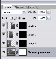
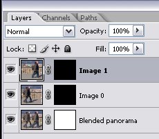
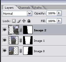
This file structure is very useful when the source images don’t connect perfectly (freehand shooting), or when there are moving elements on the scene. In the following picture you can see a panorama composed by three images that I’ll use as example, and sideways the relevant layer structure produced by PTGui:
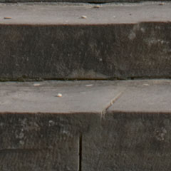
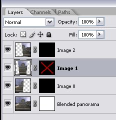
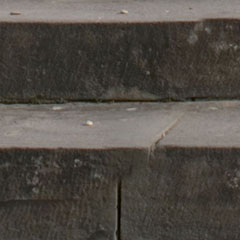
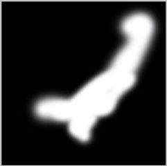
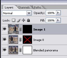
As you can see, every layers has his own level mask. The lower level, which includes the finished panorama, has a mask that displays the whole image, except for areas without information. The higher levels hold single source images that would cover the layers below, but the relevant level masks are completely black so they actually dont' affect the displayed image. The Stitch is executed freehand, so images don't joint perfectly, in particular for closer objects. The Blender has created a blended panorama in which these mistakes are hidden everything possible, but it’s clear that connection faults are visible over a certain threshold. Using “Blended Panorama only” output, the probable connection problems have to be seek examining with attention the whole image, that is an inconvenient and tiring operation. Instead, using the “Blended and layers only” output option, it’s possible to superimpose temporarly the single images levels, to immediately display the possible differences between the blended version and the original image. To perform this check it’s sufficient a Shift+Click on the interested level mask (with left mouse key). In this case, opening “Image 1” layer I noticed a not well done transition, in the area of closest stairs:
b. = The same particular, original version recorded in the mid image (Image 1)
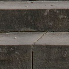
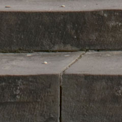
This is the procedure: - re-activate the layer mask of “Image 1” (with Shift+Click) In the following picture you can see the correction effect, examining the layer mask, the transition line between images and the resulting image:
b. = situation after manual corrections on layer mask of “Image 1” (with Eraser tool) The transition has been moved in a zone without geometric elements, where the observer 's eye has not references to identify it. Problem solved !
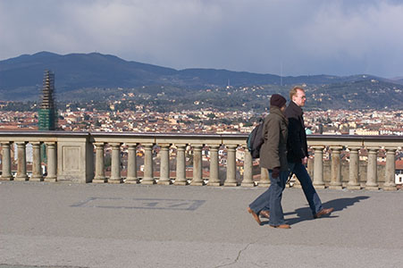
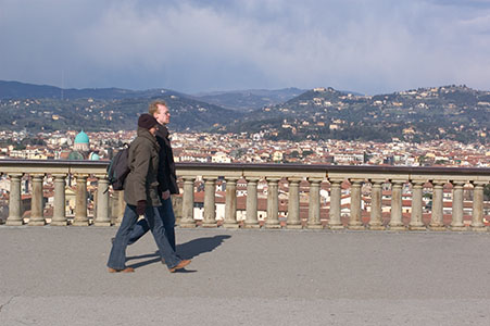
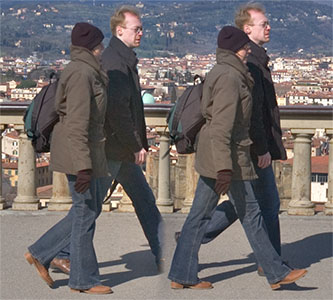
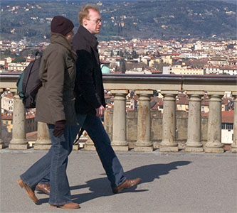
"Blended and Layers" output option: management of moving elements. The “Blended and layers” output can also be useful to manage panoramas with moving elements, as par example, a crowded square. If a walking man is photographed two times in two different panorama's images, there are only two possible choices: to leave the person appearing two times (sometime the problem is not so evident) or try to clone him with the “Clone Stamp” tool. When the walking man is located on the transition between two images, the situation is more complex because the Blender could create an image with evident artifacts and also with a wrong tonal correction. In these cases I suggest to select the “Blended and Layers” output and create the Stitch de-activating “Colour correct layers” option, however paying attention to carefully correct the original releases, with particular attention to the lens vignetting; shooting in RAW format, it’s possible for example to operate in the "lens" panel of Adobe Camera RAW. As an example, we will create a panorama of the two following images, shooted with hand-held digital camera: A titolo di esempio, realizzeremo lo Stitch dei due seguenti fotogrammi scattati a mano libera (anche se ovviamente il caso costituirebbe una situazione reale solo in presenza di altri soggetti in movimento presenti nell'inquadratura):
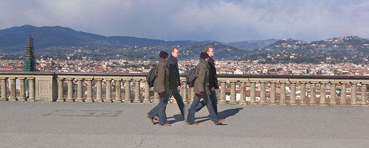
This is the PTGui blended panorama :
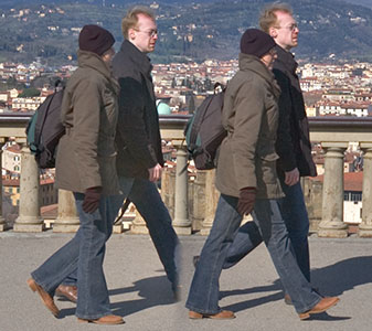
Apparently the only problem to solve is the expected duplication and the partial superposed subjects, but after a deepen check we find other artifacts:
b. = the same detail, original version from left image (Image 0 )
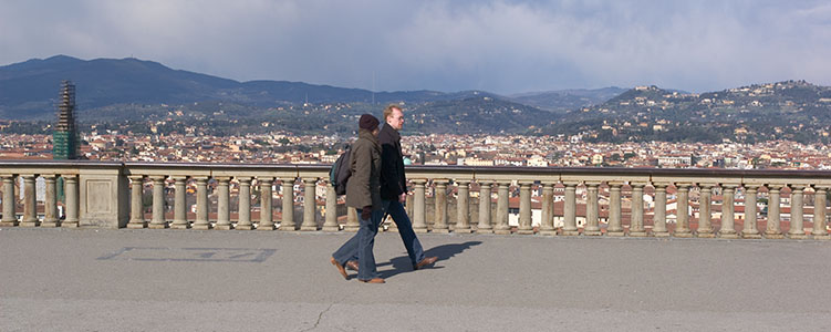
We note that the Blender has flattened the dress tonalities as for girl and boy, probably because the software try to homogenize the two original images tonality, also where containing different scene informations. Another problem is the column between the two couples, that appears very compressed because of the parallax error (I haven't rotated the camera around it's lens nodal point). Thanks to the choice of “Blended and Layers” output, all these problems are solvable using the “Erase tool” of Photoshop. Let’s see how: Grazie al fatto di aver scelto l'uscita "Blended and Layers", tutti e tre i problemi sono risolvibili utilizzando con astuzia lo strumento "Gomma" di Photoshop. Vediamo come:
b. = The same detail after the editing with the "Erase tool"
With the editing of “Image 0” layer mask, we recovered the original tonalities of the couple ad erased the left couple, recovering the original background. In this manner we also have moved the transition between the two images: while the initial image showed a "compressed" column, the artifact has been moved away from “attention area” and now it consists in two columns nearer than all others. Here is the final panorama :
A final observation: it’s clear that the importance to plan big overlapping areas between images. For normal panoramas a 20-30% overlapppig is more than sufficient, while when we have moving subjects I suggest to increase the overlap up to 50%. In this way we will realize more images but we'll have a better management of the transitions.
The “individual Layers only” output is the third option to create the final panorama, but probably the less used. The reason is that the output file will hold only the original images, properly warped but not color corrected, without the blended image:
As you can see, there isn’t an effective transitions management, so that the seams from an image to another appear very evident. The only solution to improve the panorama is to “soften” the transition, using a soft brush on the layer masks edges. The brush can have larger sizes on low detailed zones (as the sky), while on the detailed zones I suggest to reduce its size, to avoid seams with evident definition loss. The reproduction each part of this article is prohibited, without the author's permission. |